Linkages
Contents
Fourbar
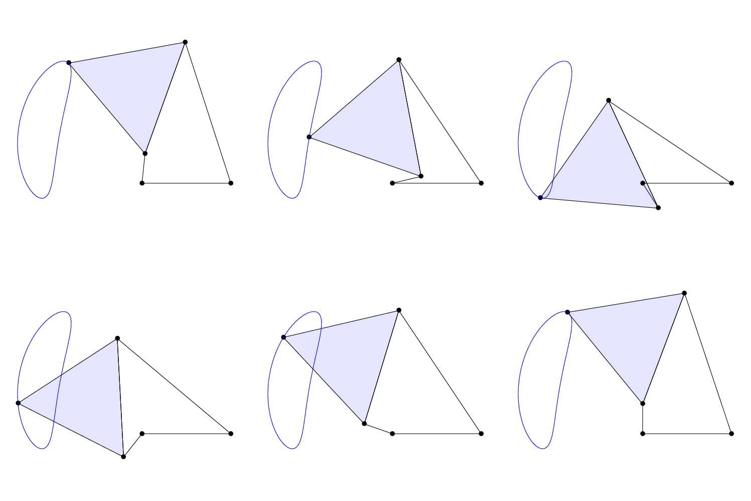
A fourbar linkage is the simplest movable mechanism. It consists of four entities, know as links or bars that are connected by joints in a closed loop. The fourbars described in the lab have joints that are only one degree of freedom and the links all exist in parallel planes, otherwise known as a Planar fourbar.
The links of the fourbar can be further broken down by the name of each link. The ground link is the only stationary link of a fourbar this is then attached to two other links, the crank and the follower. Of the two, the crank is the "powered" link, the link that is currently driving the motion, thereby making the second link the follower. The final link, which connects the other end of the crank and the slider, is known as the coupler.
Grashof Condition
A fourbar is considered to be Grashof if the shortest link can rotate fully with respect to a neighboring link. This is determined to be true by comparing the linkage lengths in the following equation:
Where S is the shortest link, L is the longest,and P and Q are the remaining two links.
Slider Crank
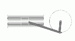
A slider crank fourbar is different from a regular fourbar in that the follower linkage slides along a channel as opposed to being a bar, know as a slider. The other remaining links follow the same naming convention as listed above. A slider crank fourbar cannot be classified as Grashof or non-Grashof.
Sixbar
Sixbar linkages are mechanisms that are constructed from six liks and seven joints where each joint connects two links and two of the links have an additional joint along them. There are two classifications of the six-bar linkage, Watt and Stephenson. Watt sixbar linkages are defined by its two fourbar loops. Stephenson linkages contain one fourbar loop and one fivebar loop.
Mobility
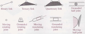
Mobility, otherwise known as Degrees of Freedom (DoF), is a term used to define the geometric constraints that limit a mechanical system. Each DoF represents a specific linear or rotational motion that can be changed by the system. Initially, any one body of a system has 3 degrees of freedom, two linear and one rotational, which are then further constrained by the connection of joints. There are two types of joints when discussing a planar system, full and half joints. Full joints allow movement through only one degree of freedom and half joints allow movement through two. The type of link has no bearing on a systems mobility other than increasing the number of possible joints.
A systems total mobility can be determined mathematically, which is the method that you will be using in lab. The equation is as follows:
Where L is the total number of bodies in the system j1 is the number full joints and j2 is the number of half joints.


