WPI Arduino Shield
Contents
Introduction
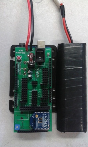
The WPI Arduino shield is designed to power and connect motors, sensors, batteries, and controllers to the Arduino Mega. The shield has been designed to provide power from a hobby style 7.2V battery to 8 servo ports limited with a 7.5 amp car style fuse. It provides Vin for the Arduino mega, and has a 5v regulator to provide power to sensors through a 1 amp auto reset fuses. Associated libraries can be found at WPI Arduino Libraries
RBE 1001 shield
Layout
The layout is meant to be straight forward and simple.
- The 3-pin ports on the top right labeled S# are designed for servos. They provide the Vin (7.2V battery voltage) to the center power pin limited with a 7.5 amp fuse.
- The 3 pin ports below the servo pins labeled int# are the interruptable pins. The center pin is a regulated 5 volts with a dedicated 1 amp auto reset-able fuse. The Int21 port is a 4 pin port that breaks out the I2C interface. The pins from left to right: 20(SDA), 21(SCL), 5V, Gnd.
- The D# 3-pin ports located in the center are general digital I/O pins. The center pin is a regulated 5 volts with a dedicated 1 amp auto reset-able fuse.
- The A# 3-pin ports located on the left side of the board are the analog inputs. The center pin is a regulated 5 volts with a dedicated 1 amp auto reset-able fuse.
- At the bottom of the analog pins you will find and SPI port.
- The ON/OFF switch only affects battery input, not USB. If the switch is off or the battery is disconnected you may see ~3V on the 5V pins.
- The Xbee socket on the lower end of the shield is connected to Serial1 on the arduino Mega for the wireless gamepad. Pins 18 and 19 on the arduino.
- The potentiometer and LCD port allow you to control a parallel liquid crystal display using pins 40,41,42,43,44,45
- The reset switch resets the arduino.
- The shield was designed with a 7.5 Amp fuse to prevent damage.
Special notes
If the switch is off or the battery is disconnected and the USB cable is plugged in you may see ~3V on the 5V pins.
Vin is 7-9V and should not be used to power additional circuits.
Schematics
PCB
File:Arduino sheild all 1page.pdf
RBE 200x Shield
Introduction
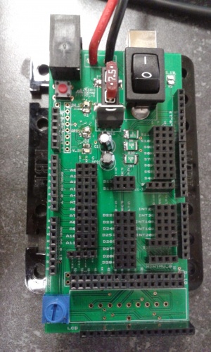
The RBE 200x Shield is an expanded shield for the Arduino Mega 2560. This shield has an improved power circuit, A reduction of LED's, a more robust layout, and additional ports.
Layout
The layout is meant to be straight forward and simple.
- The 3-pin ports on the top right labeled S# are designed for servos. They provide the Vin (7.2V battery voltage) to the center power pin limited with a 7.5 amp fuse.
- The 3 pin ports below the servo pins labeled int# are the interruptable pins. The center pin is a regulated 5 volts with a dedicated 1 amp auto reset-able fuse. The Int21 port is a 4 pin port that breaks out the I2C interface. The pins from left to right: 20(SDA), 21(SCL), 5V, Gnd.
- The D# 3 pin ports located in the center are general digital I/O pins. The center pin is a regulated 5 volts with a dedicated 1 amp auto reset-able fuse.
- The A# 3 pin ports located on the left side of the board are the analog inputs. The center pin is a regulated 5 volts with a dedicated 1 amp auto reset-able fuse.
- At the bottom of the analog pins you will find and SPI port.
- The ON/OFF switch only effects battery input, not USB. If the switch is off or the battery is disconnected you may see ~3V on the 5V pins.
- The reset switch resets the arduino.
- The PPM port connects a vex transmitter to pin #2.
- The shield was designed with a 7.5 Amp fuse to prevent damage.
- There is a 4 pin Header with the pin out for a Bluetooth slave device.
- There are also 2, 4 pin headers one for the MiniIMU and one for general I2C
- The potentiometer and LCD port allow you to control a parallel liquid crystal display using pins 40,41,42,43,44,45
- The large unlabeled port is design to interface a PlayStation controller.

