Inputs and Outputs
Contents
Inputs and Outputs (IO)
All programs work on an Input / Output basis, whether it is a PC based program taking in a joystick and outputting the commands to a game character or a microcontroller that flashes an LED when a button is pressed. Arduinos support a number of inputs and outputs.
Inputs
Inputs are essential and vary greatly.
There are several different ways to get an Input with an Arduino.
Analog
Analog Inputs Vary from The voltage source to ground. With most Arduino boards they output a value between 0-1023 linearly proportional to the voltage. Example on a 5V Arduino 0V=0, 2.5v=511, 5V=1023.
int sensorValue = analogRead(pin #);
This line of code would initialize a variable type int with the name sensorValue and make it equal to the analog signal on the pin
Digital Input
Digital Inputs are pins that can detect whether the pin is at VCC (source voltage) or GND. The barrier threshold can vary but it usually lies at about half of VCC. There are two lines of code that are important for using a digital input.
pinMode(pin #,INPUT);
pinMode is a function that sets up a digital pin. The pin number can be any pin that is not in use. The second parameter has 3 options INPUT, OUTPUT, or INPUT_PULLUP.
With standard INPUT the pin will float which means it can change state without a change if the pin is left disconnected.
Interrupts
Interrupts are used for handling time sensitive inputs or outputs. It is important to never put a delay or print statement inside the interrupt. The best way to print or delay after an interrupt is to use a flag. A flag is a variable that is changed in the interrupt that will make something happen in your main loop.
To initialize the interrupt you need to add this line to the setup.
attachInterrupt(0, blink, CHANGE);
The first parameter is the interrupt number. The interrupt number is not the pin number except on the Arduino due. Interrupt 0 = pin2 on the Uno. The second parameter is the function that will be called when the pin triggered. It needs to be defined outside the setup and loop functions.
void blink()
{
state = !state;
}
The third parameter is the trigger setting. You can have it run the code in blink on the “RISING” edge, “FALLING” edge, or “CHANGE”.
Outputs
Outputs are essential for controlling devices. There are three, pin level outputs with the Arduino.
• Servo
Digital Outputs
A digital output is used to switch a pin from ground to the VCC or vice versa. To use a digital output simple tell the Arduino you want the pin to be an output with this line in setup
pinMode(Pin #, OUTPUT);
And set it High(1) or Low(0) with this commad
digitalWrite(pin #, HIGH);
PWM
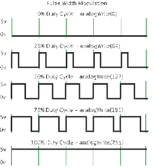
Pulse Width Modulationis the act of changing the width of a pulse and has a number of uses. The most common use is to fake an analog output signal. The idea is that if you switch a pin fast enough with the appropriate duty cycle you can fool an analog input to see voltages between 0 and Vcc. This is achieved by the analogWrite command. This command outputs a 490Hz wave that changes duty cycle based on the input 0-255.
To use the analogWrite function simply enter
int value=127; // 0 to 255
analogWrite(pin#,value); //to start or update
Servo
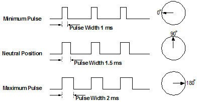
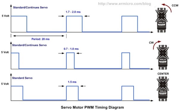
The Servo library allows for control of servos and motor drivers that use the servo signal including VEX servos and Vex motors. The Servo signal is another form of PWM. The signal for a servo is a digital output that pulses once every 20 milliseconds. The length of the pulse is equivalent to the direction the servo will point or speed and direction of a motor. The pulse is between 1000 microseconds and 2000 microseconds with 1500 microseconds being the middle of a servo or stopped for a motor. To use a servo there are 4 steps. The Arduino will output a 500us to 2500us signal by default. Refer to step three for how to change the default.
Step 1: Include the servo library outside of any loops at the beginning of your program
#include <Servo.h>
Step 2: Create a servo object. An object is just a variable with multiple attributes and functionality.
Servo myservo;
Step 3: Attach your servo object to a pin(parameter 1) and limit the output pulse to between 1000 microseconds and 2000 microseconds(parameter 2 and 3). The 2nd and 3rd parameters are required on Vex 269 and 393 motors for reliable behavior.
myservo.attach(9,1000,2000);
Step 4: Update or “write” a value between 0 and 180 to the servo.
myservo.write(val);
Servo
Top     = 	myservo.write(0);
Middle	 =	myservo.write(90);
Bottom	 = 	myservo.write(180);
Servo Motor
Top  		=  myservomotor.write(180);
Middle		=  myservomotor.write(0);
Bottom	 	=  myservomotor.write(90);


