Gears
Gears are used to transfer motion. They vary greatly in configuration and are used for many different purposes. The basic premise is that the input gear (driven gear) has a set number of teeth and the output gear has a set number of teeth. The ratio between these two gears can be used to find the torque and speed of the output gear if the input to the driven gear is known.
Contents
Torque vs. Speed
Speed and torque are inversely proportional. The radius of a gear is directly proportional to its torque.
- Speed = ( Input gear / Output gear ) * Input Speed
- Torque = ( Output gear / Input gear ) * Input Torque
- Torque = a * Gear radius
- Torque Gear 1 / Radius Gear 1 = Torque Gear 2 / Radius Gear 2
Example
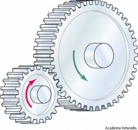
An example will go a long way. If there was a motor attached to a 10 tooth spur gear that spins at 100 rpm with a torque of 1 in/lb and 1 in radius. And you mate a 20 tooth spur gear to the 10 tooth gear. The the output from the 20 tooth gear would be 50 rpm with 2 in/lb. of torque and 2 in radius.
- Speed: ( 10 / 20 ) * 100 = 50 rpm
- Torque: ( 20 / 10 ) * 1 = 2 in/lb
- Radius: ( 2 * 1 ) / 1 = 2 in
spur gears
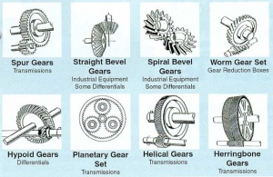
The most common and simple gears are spur gears. “Straight cut” gears are used to transmit rotational force (speed and torque) to another gear or rack (flat gear). Spur gears come in many materials, with various hubs and pitches. Hubs are the center portion of the gear used to attach the gear to its shaft. The diametric pitch is the number of teeth per inch for a gear. This is easy to visualize with the rack and pinion gear below. If the pitch was 24, then there would be 24 rack teeth in 1 inch (unless it was metric, then 24 teeth per centimeter).
Planetary Gears
Planetary gears or epicyclic gears consist of a ring gear, one or more outer gears (planet gears), revolving around a central gear (sun gear). Typically the ring gear would be attached to an arm or actuator. But any of the three gears can be stationary allowing a lot of different configurations. The main advantage to this gear arrangement is high reductions in a small amount of space, compared to standard spur gear arrangements.
Bevel Gears
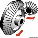
Bevel gears are very similar to spur gears except they are intended to transfer rotation through a 90 degree translation. The bevel gears make a 90 degree transition easy but it does require a strong gear box. The speed and torque are treated the same in a bevel gear as they are in a spur gear.
Worm Gears
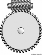
Worm gears are also used to transfer rotational force through a 90 degree transition. Worm gears are non-back drivable. This means that no matter how much force is applied to the large spur like gear the driven worm gear will not move. Worm gears tend to have very high ratios between its input and output. The driven gear is a spiral that moves the output gear 1 tooth for every rotation of the input. If the output gear had 30 teeth then the ratio would be 30 to 1. You can use this ratio in the torque and speed equations in the spur gear section.
Lead Screws
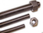
Lead screws are basically a long screw with a nut used for linear motion. A lead screw has a high mechanical advantage, low efficiency (50%), large load capability, precise and accurate linear motion, and most are not back-drivable. The high friction usually requires lubrication and tends to overheat or break down in long term continuous movement.
Ball Screws
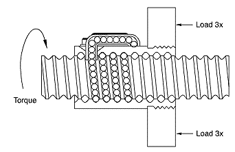
Ball screws are basically a lead screw with bearings in the “nut”, used for linear motion. A ball screw has a high mechanical advantage, high efficiency (90%), large load capability, precise and accurate linear motion, and most are back-drivable. The balls screws are more expensive but can usually pay for themselves in the long term with their longer lifespan and reduced maintenance.
Idler gears
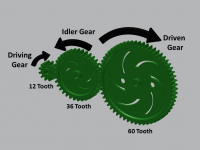
Idler gears do not affect the ratio. Idler gears are used to space a reduction differently or to invert the direction of rotation. The gear in the center is the idler gear and makes no difference to the ratio between the gear on the left and the right.
Compound Spur Gears
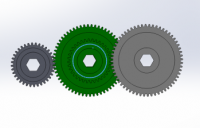
Compound spur gears are just spur gears with two sets of teeth used to increase ratios. The pictures below depict the arrangement. To find the ratio you will need to find the ratios between the two spur gear arrangements and multiply them together. The green gear represents the compound gear.
10 tooth to 40 tooth = 1/4 speed
Then 10 tooth to 40 tooth again = 1/4 speed
Final ratio is 1/4 x 1/4 = 1/8 x speed
And or 8/1 x torque
