Operational Amplifiers
Op Amps or Operational Amplifiers are used for many different purposes. They are used as buffers, inverters, amplifiers, comparators, level shifters, Digital to Analog converters, and Analog to Digital converters.
Contents
Typical Layout
The circuit symbol for an op-amp is shown to the right, where:
- V+: non-inverting input
- V−: inverting input
- Vout: output
- VS+: positive power supply
- VS−: negative power supply
The power supply pins (VS+ and VS−) are often these pins are left out of the diagram for clarity, and the power configuration is described or assumed from the circuit.
Comparator
The amplifier's differential inputs consist of a V+ input and a V− input, and ideally the op-amp amplifies only the difference in voltage between the two, which is called the differential input voltage. The output voltage of the op-amp is given by the equation:
Where V+ is the voltage at the non-inverting terminal, V− is the voltage at the inverting terminal and AOL is the open-loop gain of the amplifier (the term "open-loop" refers to the absence of a feedback loop from the output to the input).
Note: The magnitude of AOL is typically very large—100,000 or more for integrated circuit op-amps—and therefore even a quite small difference between V+ and V− drives the amplifier output nearly to the supply voltage.
Non-Inverting Amplifier
In a non-inverting amplifier, the output voltage changes in the same direction as the input voltage.
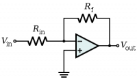
Inverting Amplifier
In an inverting amplifier, the output voltage changes in an opposite direction to the input voltage.
Buffer/Voltage Follower
This circuit is used to buffer a high impedance source. Use this circuit to eliminate loading effects.


