Oscilloscope for beginners
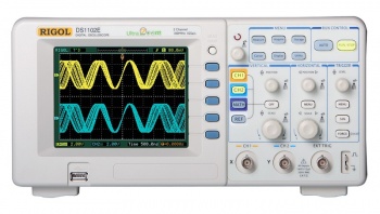
Oscilloscopes or “O-scopes” are used to measure electrical signals over time. They represent the electrical signal with a wave or line that is equivalent to the voltage on the scope probe. An oscilloscope is just a real-time graph of voltage over time.
Oscilloscope Layout
The layout described is for the oscilloscopes in the RBE lab.
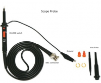
The scope probe is used to connect the scope to your electrical circuit. The BNC connector is attached by pressing it into the connector on the scope and turning. The alligator clip is your ground connection and must always be connected to your circuits ground. The witch hat goes on the end of the probe and allows you to easily connect to things by simply pressing it down. Do not remove the witch hat.
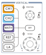
The vertical scale or voltage is controlled with these two knobs. The position knob will adjust where the signal is in the vertical direction. The scale knob adjusts how many volts each vertical block represents. The buttons on the left are for selecting which channel you are editing.
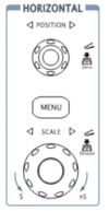
The horizontal scale or time (shown on the left) is controlled with these two knobs. The position knob will adjust where the signal is in the horizontal direction. The scale knob adjusts how many seconds each horizontal block represents.
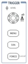
The Trigger (shown on the right) is used for stopping and examining a signal. The trigger will look for whatever threshold you set and hold the signal still for viewing and examination.
Signals
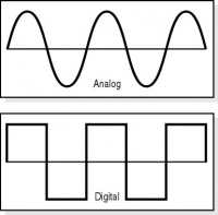
Signals generally fall into two categories: analog or digital. Analog signals vary in voltage between the source and ground. Digital signals are either source voltage or ground.
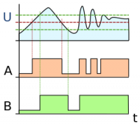
The threshold for digital signals can vary but the threshold is normally about half of the source voltage. With the AVR in the Arduino the threshold is 2.4V on the way up and 2V on the way down. This allows many 3.3v digital signals to be read by the 5v device.
Analog signals are read using analog input pins and return a value between 0-1024. The voltage can be determined by the value returned multiplied by the voltage source (5v) and then divide by 1024.
Voltage = ( analogRead() * 5 ) / 1024
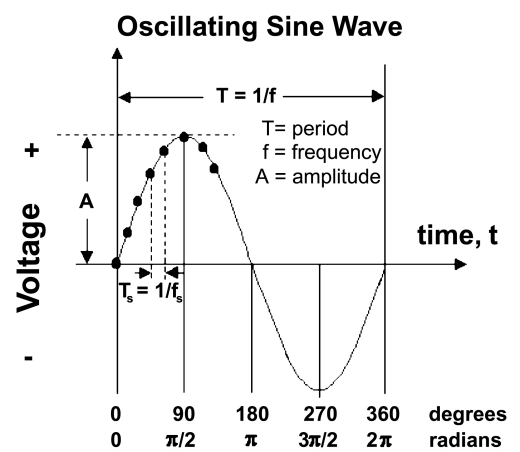
The two other important signals characteristics are rise and fall times and frequency. The rise and fall time are just how long it takes the signal to settle. The frequency is determined by finding the period of each cycle. The period is basically how long it takes a signal to repeat. The equation for frequency is
Frequency= Cycles / time
Digital signals are used in most communications. A digital signal will either be high (1) or low (0). The duty cycle is an important characteristic for some digital signal. Duty cycle is the time high over the time low.
Duty cycle = time high / time of signal
